Saturday, January 2, 2021

Astrophotography with Inside Education

During the 2019 - 2020 school year 25 students from Jasper Place were given funding courtesy of Inside Education to learn about Energy by engaging in Astrophotography. In addition to these students, we engaged with roughly a dozen outside members of the community including several astronomy and physics professors, amateur astronomers and other students. The students in my astronomy class first developed a solid foundation of the basics of astronomy and astrophysics in their classrooms. They used DSLR cameras, cellphone cameras and got comfortable using telescopes during weekly stargazing sessions.  

These hands on activities were combined with detailed lessons on the Physics of astrophysics and the energy conversions involved when stars, nebulae and galaxies produce light, how that energy is transmitted to Earth and then how it interacts with detectors.  After about 2 months of education in the basics of astronomy and astrophotophotography, students put their skills to the test and were given telescope time on the iTelescope network.  These telescopes were remotely controlled over the internet and allowed students to access 23 different telescopes as far away as Spain or Australia. 

Students were tasked with researching an astrophysical object they were interested in photographing, decided on the appropriate imaging parameters (exposure time, filters, telescope) and entering their observations into the iTelescope network.  Once the images were taken students were then responsible for post processing which involved stacking images and adjusting/stretching images using Photoshop.  

Once students completed these tasks they had to provide a description of what they observed, the physics behind the production of the light and suggest ways this information has or could be used to help better deal with energy related issues here on Earth. 

Several of the students photos are showcased below.


In addition to taking the photos and editing them, the students were also responsible for researching the astrometry (the location in the sky along with actual position relative to Earth) and the physics responsible for the light produced by the objects in the image.

This project provided several positive impacts related to energy education in our community. Throughout this project students thought of energy as something they needed to capture and conserve.  They developed an understanding of how energy is produced in astrophysical settings and saw that there were numerous ways we could apply those same processes here on Earth.  For example, after reviewing her photos, one student commented that "If we use nuclear fusion and gravity as power sources, we could have immense technological advances for spacecraft, transportation, and agriculture. We could also learn how to harness energy without polluting the atmosphere."

Other students commented on how capturing light on cameras seemed very similar to solar panels. "If we can take photos of light (energy) with a camera, shouldn't we be able to do the same thing to power our homes?" One student even commented, after researching how light was produced in other galaxies that solar power was really just nuclear fusion at a same distance. Other more fantastical ideas involved research into dark energy or matter as a power source, "Currently, dark energy is shrouded in mystery, but one day hopefully scientists would uncover the secret and then we will have a renewable ecological source of energy". Although this may not be grounded in our current knowledge of Physics, the desire to explore new and emerging sources of energy is one that will be increasingly necessary as our society demands ever greater power supplies.

Although we had to cut the project short and didn't have the chance to fully present the results of our project, the students were constantly immersed in the project, learned a great deal about the physics of energy transitions and developed a thorough understanding of the uses of energy.  I'd like to thank Inside Education and iTelescope.net for the amazing learning opportunities they gave my students!

Saturday, January 20, 2018

All Sky Observations

Recently one of my Astronomy Students and I built an All Sky Camera and a weather proof enclosure.  The camera is now mounted on the roof of the high school I work at and can be accessed remotely; using Teamviewer, I can log in to the computer its connected to and operate the camera from pretty much anywhere.  The video below is an hour time lapse taken on the evening of January 18th through a break in some pretty heavy clouds. I've created a YouTube Channel where I'll upload all (or maybe just interesting) videos the camera takes.  You should really subscribe to it-


 https://www.youtube.com/channel/UCp88WNakv30zIe6i12XasDA


Camera is in the lower left corner

Constructing the enclosure was pretty straightforward- mostly because I didn't do it myself.  Fortunately, one of other students was taking woodshop as an option course and he offered to build it.  Construction was very simple.  Its just a wooden base with a hole for the cables and another hole for the screw that holds the camera in place. The base sits on two wooden legs that allows the cable to pass underneath.  Since the camera will be outside, all the wood has been weather proofed.  The camera sits inside an acrylic dome I purchased from amazon for $15.99. The dome came with a plastic ring that provides an airtight seal once the dome is screwed on.


The camera is a ZWO 120MC colour camera.  Its screwed onto the base plate with a 3" M10 screw.  The USB cable passes through a small hole on the bottom of the base plate.  The whole was sealed with a combination of steel wool and silicone.  To combat dew forming on the inside of the dome we did some I considered pretty ingenious.  The week that the camera was completed the temperature plunged to near -40 oC. Air that cold hardly holds an moisture so we took the camera outside and removed the dome.  After a couple minutes we resealed everything with the  -40 oC inside.  So, with a little luck, there will be little to no dew on the inside of the dome at night.

With the camera complete, it was placed on the roof of Jasper Place.  A 20" active repeater cable was used to connect the camera to a laptop computer that runs SharpCap and has Teamviewer installed.  Using this software combination, anyone with the right password (which will really only be me!) could control the camera.

So far its been pretty cloudy here in Edmonton so we haven't really had any opportunities to take pictures of anything Astronomical in Nature.  Once the clouds clear we'll hopefully be able to image meteor showers and Aurora (and maybe even a UFO!).

Since placing it on the roof I have noticed one problem that will need to be addressed.  In the winter in Edmonton it gets pretty chilly and frost is a big problem.  I though that the waste heat from the camera would be enough to keep the dome from frosting over but I was wrong.  So I'm in the process of designing a rudimentary USB powered heater that will try and fight off the frost. And then its just a matter of waiting for some clear skies!


Sunday, October 8, 2017

KIC 8462852 and Photometry

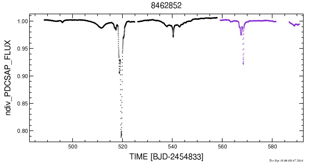
https://ksr-ugc.imgix.net/assets/011/194/412/aca327283289f957b57825ad326ee949_original.png?w=680&fit=max&v=1463167667&auto=format&lossless=true&s=2ac5ed979e8b97dfabeaec7c0dc69490In September 2015 a star in Cygnus was observed by the Kepler Satellite; unlike the millions of other stars observed in the Kepler field of view this star demonstrated a very unique light curve. And unlike many of the interesting transits found by Kepler the first identification was done by Citizen Scientists on planethunters.org. This marked a major milestone for crowd sourced science and provided an amazing collaboration between professional and amateur scientists.

The star, KIC 8462852 (also known as Tabby's Star), is a seemingly normal F-type star in the constellation Cygnus.What makes it unusual is the seemingly unpredictable nature of its luminosity.


Stars that change their brightness are not uncommon and there are in fact many reasons why brightness may change.  This can include intrinsic variations of the star's brightness due to Star Spots or compositional changes like Cepheid variable stars.  Or it may be due to another companion nearby; Algol in the constellation Perseus is a well known example of this.  In the last 10 years the idea of eclipsing stars has been applied to the search for extrasolar planets- as a planet passes in front of it's parent star (or transits) it causes a small dimming of the star.  The dimming is very slight; Jupiter, the most massive planet in our solar system would produce a dimming of around 1%.  Smaller planets like the Earth or Mars would produce dimming less than 0.05%.  Despite these tiny changes in light, the variations are within the range of modern digital cameras and using this technique the Kepler satellite has discovered thousands of exoplanets.

What makes KIC 8462852 unusual is both the degree of dimming (depth) and the seemingly random nature of its dimming.  Unlike other exoplanets there does not seem to be a regular period dimming (which would be caused by a planet moving in a circular orbit). In addition, the depth of some of minimums has been as much as 20% of the star's brightness!

Image result for kic 8462852 light curve

There have been a few attempts to explain the light curve:
  1. Young Star with an asymetric dust ring
  2. Planetary collision resulting in debris in the system
  3. Comet swarms passing through our line of sight
  4. Ringed planet with asteroids in front and behind it
  5. An Alien megastructure (Yes.  Aliens!)
 Right now there are no concrete answers.  To rule out different hypothesis more observations are needed.  With the help of the U of A, Kings University, and Athabasca University 4 students at Jasper Place high school have embarked on a journey of discovery! They are making observations of the star and analyzing the results.  Along the way they are building their own light curves in an attempt to learn about the nature of this bizarre star and help solve one of the many mysteries in Astronomy.  

Monday, May 1, 2017

Astronomy Pi and Barndoor Trackers


Most amateur astronomers are familiar with the idea of a Barn Door tracker or some similar.  Building a simple tracking device requires nothing more than a hinge (such as from a barn door), two pieces of wood and screw that can be turned.


Building a Tangent Arm tracker is very simple and only involves a few steps and materials.

Tangent Arm Tracker
·         ¼” MDF board
·         Heavy Duty Hinge
·         Screws
·         20 Thread Per Inch ¼” Threaded Rod
·         ¼” Bolt
·         ¼” Nut Cap
·         Counter Weights


Construction Steps

1) Using a suitably sized hinge, connect two pieces of wood.

2) Drill a hole about 2/3 of the way from the hinge.

3) Set a nut into the hole and glue it in place (I used a simple two part epoxy but any metal/wood glue will work).

4) Thread a coupler through the net.

5) Attach a crank to the end of the coupler.

You now have a simple Tangent Arm tracker.  The downside to this design is that if the coupler is turned at a constant rate the angular velocity, the rate the hinge opens, will not be constant.  To track for long periods of time (more than about 30 seconds) the rate the hinge opens must equal the sideral rate.  With a Tangent Arm Tracker this requires the screw to turn at ever increasing rates (and limits practical tracking to about 3 hours).

A simple DC motor could be attached to the coupler but adjusting the rotation rate is very difficult. Fortunately I came up with an alternative! A list of the materials I used for the Smart Tracker are below:

Computer Assisted Controller
·         Raspberry Pie
·         Adafruit Motor Control Board
·         Stepper Motor – NEMA size 17
·         Stepper Motor Axle Coupler

·         ¼” MDF board

Using a Raspberry Pi connected to a Stepper Motor I wrote a simple Python Script that allowed the motor rotation rate to speed up to allow the hinge to open at a constant angular rate.  The Python Code I used is below:


If you want the Python Code you can download it here.

Depending on the specifics of your Tracker the given code will cause the motor to increase its rotation too quickly or too slowly.  Fortunately, with a bit of trial and error that is easy to correct.  The number that is circled in Red controls the rate of motor increase.  By increasing or decreasing it (and saving the code after each change) you can tweak the code for any individual mount.


The photo to the left shows the Tracker with my DSLR camera attached using a simple Bogen Ball.  The motor is just visible at the bottom of the picture.

Once I had the motor connected to the Raspberry Pi, I had to align the Tracker.  In the same way the Polar Axis of an Equatorial Mount must be pointed at the pole, the Hinge Axis of the Tracker should be pointed as close to the pole as possible.  A simple polar scope or sight would be a nice addition but all I did was take an series of 10 images and use them as a quasi-drift alignment.

The first image series, shown below, was done without the motor on. All images were taken with a Canon xTi with a 200 mm lens.


Calibration Image

This series allowed me to test how effective the motor was and adjust both the polar alignment and the motor drive rate.  There are three pictures, spaced out over 3 minutes.  During that time the star moved approximately 1/2 across the field of view of my DSLR camera.


First Tracking Attempt

After turning the motor on I superimposed the previous series on the second series.  The angle between the Sidereal Motion and the second series allowed me to estimate how much I needed to move the polar axis as well as quantify both the on and off axis motion.  Next I adjusted the pointing of the axis and slightly increased the rate the motor was turning at.


 Final Tracking Attempt

After several interation of this procedure (which really only took about 20 minutes, not including the last imaging series which was 30 minutes) I ended up with the series shown in white (these are actually the same star but are coloured differently to so they are easily distinguished).  The three red stars are the original reference series which shows the sidereal motion of a star over the course of three minuets.  When the Tracker is turned on, the white stars shows the same motion of the star over 30 minutes.

After all is said and done, I decided this was as good as I was going to get.  The polar alignment was great and RA drift ended up being sufficient for exposures of less than 5 minutes with a focal length of 200 mm.  Obviously as the focal length decreases the exposure length can increase.

The image below is of Orion and was taken using the Tracking Rig described.  Its made up of 5 x 3 minute exposures at 100 mm at ISO 800.


This led me to the one major draw back of my design.  Because it uses a Raspberry Pi it requires a computer monitor and keyboard as well as an AC power supply.  This can present a number of problems for Amateur Astronomers.  However, a simple solution would be to use an Arduino instead of an R-Pi.  However, as of yet I haven't had the time to do that.

Best of luck to all and feel free to email me with any questions.

Thursday, December 1, 2016

The Sun

Well, its been a while since I posted anything here.  I've been so busy lately (or for like the past 6 months!) so its taken me a while to post anything.

Several months ago, back in August actually, I took out my Hydrogen Alpha telescope.  Its a Coronado 60 mm double stack telescope.  This means it actually has two Hydrogen Alpha Filters on it; by stacking one on top of the other it has a much sharper image and can see finer detail in solar features.  During the summer I was able to set up the telescope together with my ASI 174 camera and take some great pictures of the sun.  The one I'm most impressed with is of an active region on the sun. The atmospheric conditions where just right and I got amazing details!


The lines running north-south are prominences seen edge one.  Around the bright yellow parts in the middle, the solar surface is curved around the sun spots.  The curving is due to the interaction of the Sun's magnetic field with the plasma that makes up the sun.  The charged particles twist and curve around the magnetic field lines in the same way they form Aurora Borealis (and Australius) here on Earth.


Saturday, August 29, 2015

Solar Observing

Summer in Edmonton means lots of long, lazy days.  Which translates into almost no opportunities for actual STAR gazing.  Unless you choose to look at the Sun.  And unless you know what you're doing its not a smart thing to do. Fortunately I sometimes actually do know what I'm doing.
Sun in White Light.  A 99.9% filter was used.  The dark spots are sun spots.

If you're ever interested in looking at the sun there are a few things you need to know.  First, and I can't stress this enough, it can be DANGEROUS.  Blindly so.  Once, several years ago, I projected the sun onto a white piece of paper to show a student what sun spots looked like.  If you keep the paper far enough away from the eye piece it is quite easy to do.  After a couple of seconds I took the paper away and was doing some explaining.  I made the mistake of  moving my hand in front of the telescope eyepiece (which was still pointed at the sun) and in less than a second I had myself a second degree burn.  The point is, unless your are confident in what you are doing, don't.  You can literally go blind.

Despite this, its actually quite easy to observe the sun.  Go to any hardware store that sells welding equipment and get a piece of Number 12, 13, or 14 welder's glass (which I'll call a solar filter from now on since that's what we're using it as).  Don't get anything less! These types of glass are dense enough to block out the dangerous UV light coming from the sun. Others are not.  Once you have said piece of glass, hold it up to your eyes and find the sun.
Sun in HA showing a nice Prominence on the right


Using Welder's glass will not magnify the sun however.  So what you'll see will probably lack any significant detail.  I have only once ever seen a sunspot big enough to see just by using a filter.  To get a better view, you could attach two solar filters in front of each lens of pair of binoculars.  Now you should be able to see some black grains on the surface of the sun.  No, your binoculars are not dirty! Those are sun spots.

For even more detail you'll need to step up to a full sized telescope with a proper solar filter (you could of course still use Welder's glass but it would be difficult to find a piece big enough; in addition I would worry about a makeshift filter falling off the telescope). Depending on the size of you're telescope you should be able to see quite a bit of detail! The surface of sun changes for a variety of reason; like the Earth, the sun rotates so we see different faces of the sun at different times.  In addition the energy produced deep inside the core of the sun is always seeping to the surface; this creates convection currents, radiation and powerful magnetic fields that shape the surface.  If you're fortunate enough to have a telescope 6" in diameter or larger you'll probably notice there are two distinct parts of Sun Spots.  The darker central part is called the Umbra while the dimmer outer layer is the Perumbra.

Sun in HA showing granulation and Spiculas and Filaments
However, none of these observational methods will allow you to observe Solar Flares or Prominences which occur in the sun's atmosphere or Corona.  To do that you need a highly specialized filter known as a HA filter.  This filter is designed to block out all the light from the sun expect the light at 656.28 nm.  This is caused by a specific transition that occurs when an electron in the third energy level of Hydrogen falls back to the second energy level (its part of what is known as the Balmer Series).  Recently I purchased a telescope with a dedicated Hydrogen Alpha Filter; a Meade double stacked 60 mm SolarMax telescope..  I haven't had more than a handful of opportunities to use it but so far the views are absolutely breathtaking!

A completely different type of solar observing involves using a Spectroscope (see my previous post on homemade Spectroscopy) to see the Solar Absorption Spectrum. The spectrum below was taken using my homemade spectroscope and calibrated using RSPEC.

Looking at the spectrum you'll see that's its not completely continuous. There are black lines, called absorption lines mixed in with the colours.  This is due to 'missing light' that was absrobed by gasses in the solar atmosphere.  By looking carefully at this spectrum and comparing it to  the spectrum of elements on Earth it is possible to find out what the sun is made of without actually going there (which would not be conducive to healthy living).  When scientists do this we find the majority of the sun is made of Hydrogen and Helium with very small amounts of other elements like Sodium, Oxygen and Iron.

All of these are exciting and interesting ways to look at the closest star to Earth, our sun!


Saturday, March 28, 2015

High Resolution Spectroscopy

This post isn't really about Astronomy but it's definitely related to the Rainbow Optics diffraction grating I bought last year.  Plus Atomic Spectra is just so cool that you can't not like it!

About six months ago a friend of mine gave me an article he wrote for the Journal of Chemical Education explaining how to build a high resolution spectroscope with materials you find around your house (with one exception). The construction process wasn't particularly difficult, but my meager woodworking skills meant it took a lot of time.  Eventually I asked one of my students to help me since he was in the middle of a woodshop course at school. 

The spectroscope itself is fairly simple.  Its a Littrow-type spectroscope that contains a single slit for light to pass through, a mirror, a lens, a high resolution diffraction grating and a focuser/lens.  After a few months I tweaked the focuser a bit so I could use a camera with it. 

The photo below is taken directly from the article (Vanderveen, Martin & Ooms, 2013) and shows all the pieces necessary to build the spectroscope.
The basic parts list as well as the approximate cost is below:
  •  1/2" plane wood ($15)
  • Screws, nuts, bolts of various sizes ($5)
  • Knife or Razor blades ($5)
  • Plane mirror ($5)
  • Collimating lens ($15)
  • Diffraction Grating ($130)
  • Focuser ($20)
  • Eyepiece ($15)


The spectroscope operation is fairly simple.  Light passes through a slit created by the two knife blades.  It is reflected 90 degrees by the plane mirror and travels through the Collimating Lens (I used an old photocopy lens).  It strikes the reflecting diffraction grating and is sent back through the lens and out to the eye piece where the spectrum can be seen or photographed. In actualilty putting everything together was a bit more challenging then it sounds; the biggest difficulty was getting the light rays to strike the mirror and diffracting grating at the right angle so it missed the edges of the lens and was sent back straight through the focuser.  All it took was a bit of tweaking but it ended up taking a lot of time.


Visually observing spectra was dead easy. However photographing it proved to be quite the challenge.  At first I was set on using my DSLR camera but that proved to be untenable.  The camera body was simply to large and in combination with the focuser I was using couldn't get the chip close enough to the lens inside the spectroscope to properly focus.  But once I switched to my Lumenera camera, which has a much smaller body, it was a breeze.  In addition to imaging the spectrum seen through the spectroscope I used the program RSPEC to further analyze it.  After some basic calibration it was clear that this spectroscope has a very high resolution.

 This is a calibration spectrum I took of a Compact Florescent light in my kitechen Despite other abient light from the windows and virtually no processing its very easy to identify several elements in the spectrum. 

Below my spectrum is a laboratory refrence of a CF bulb.  As you can see its very easy to identify the peaks!

Once the weather clears up I plan to take the entire set up outside and see if I can pull the Fraunhofer lines from the solar spectrum.  See! I told you there was an astronomy bent to this!